Adding Text to 3D Objects in Blender: A Plaque Tutorial

Turn a few words into something you can make. This Blender tutorial builds a simple Welcome plaque with raised lettering and a Celtic knotwork border, taking you from the first dimensions through to checks before manufacture.
Updated September 2026 · Blender 4.5 LTS · Full video walkthrough
A 160 × 60 mm plaque, a 150 × 50 mm knotwork area and space for your own message. You can follow the text steps on their own, or add the border using Celtic3d Knotwork Free.
Watch: make a plaque with text and Celtic knotwork
Watch the full 22-minute walkthrough on YouTube. Keep this page beside Blender as a reference for the main steps.
Jump to: Setup and dimensions · Adding text · Knotwork border · Joining the parts · Print checks · STL and millimetres
1. Start with the plaque dimensions
A quick sketch helps settle the proportions before you model. This project uses a 160 × 60 mm outline, a 5 mm base thickness, a 150 × 50 mm decorative area and a planned 130 × 30 mm space for the lettering.
- Open Blender in the Layout workspace. Save your project before you begin.
- Select the default cube. Open the 3D Viewport sidebar with N, then use Item → Dimensions to size the base.
- For the numeric convention used in this demonstration, the base dimensions are X 160, Y 60, Z 5. Read the units note below before entering these values in a different scene.
- Use a top view to arrange the design, and an angled view to check depth and contact between the parts. Keep the Outliner and Properties editor visible so you can see which object you are editing.
The demonstration uses numeric model coordinates intended as millimetres, although the scene displays metres. Celtic3d Knotwork’s own STL, OBJ and SVG exports use one Blender unit as one millimetre, regardless of the scene display. This is an export convention, not a rule for every Blender scene or exporter. See the STL checklist before sending a file to a printer.
2. Add and position your text
- In Object Mode, choose Add → Text or press Shift + A → Text.
- Select the text, press Tab for Edit Mode, delete the default word and type your message. Press Tab again to return to Object Mode.
- Open Object Data Properties, the text-data tab in the Properties editor. Under Font, use the folder button beside Regular to load a suitable font.
- Scale and move the text to fit the centre of the plaque. Check the spacing and leave breathing room around the border; the planned text area is a guide, not a target that every word must fill.
Windows font tip: fonts installed only for your account may be in %LOCALAPPDATA%\Microsoft\Windows\Fonts, rather than C:\Windows\Fonts. Choose a font file Blender can load and check its licence for your intended use.
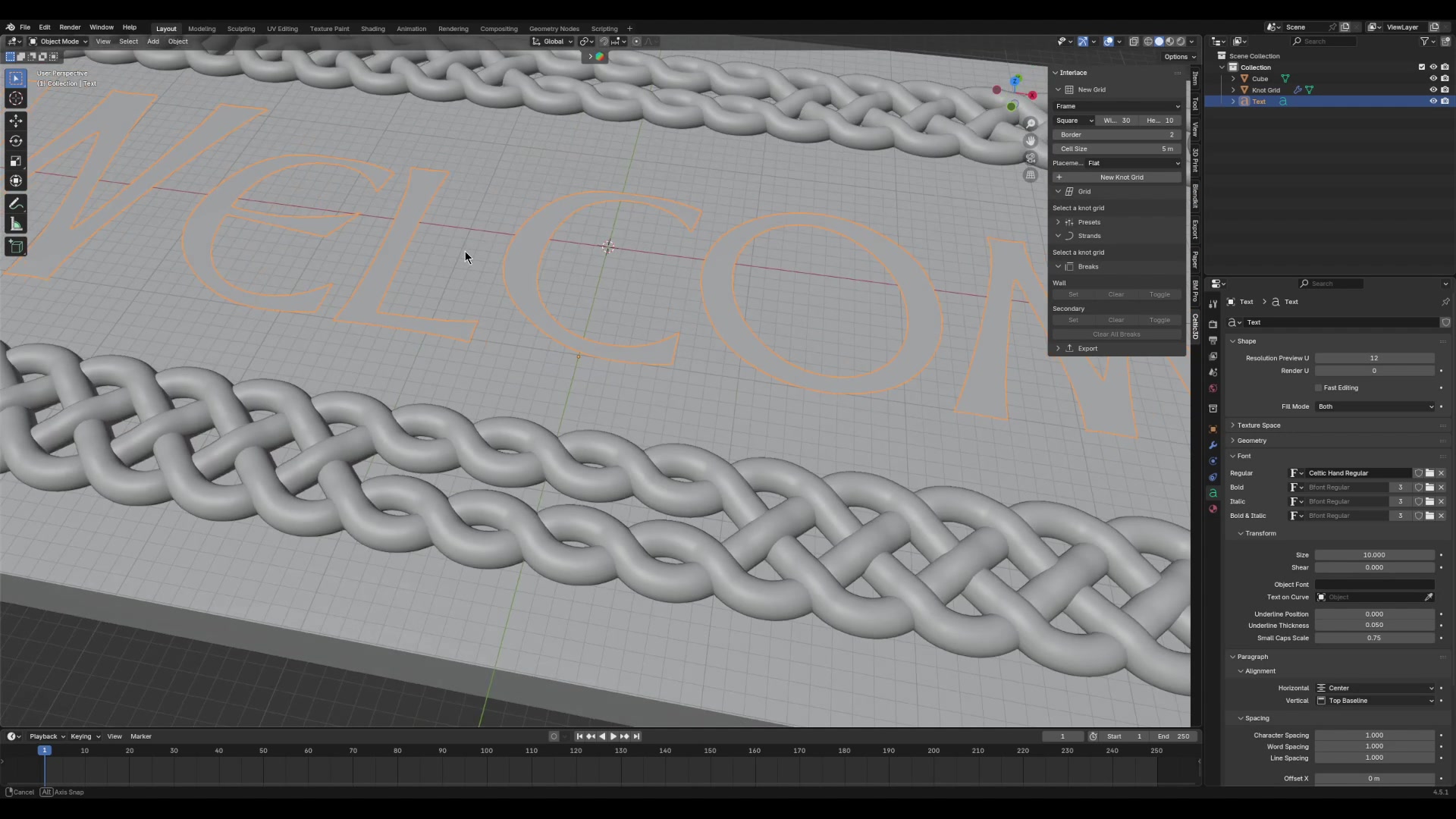
3. Give the letters depth
For editable lettering, use Object Data Properties → Geometry → Extrude to give the text thickness. Adjust the amount while looking from the side, and keep small details large enough for your intended manufacturing process.
The video also demonstrates working with converted text geometry. Before conversion, keep a separate copy of the editable text. In Object Mode, use Object → Convert → Mesh when you need mesh editing or Boolean operations. If you convert flat text and extrude it in Edit Mode, check the resulting caps and side walls carefully.
Neither route guarantees a printable mesh. Font outlines, overlapping strokes, bevels and later operations all affect the result. Choose the method that suits the lettering, then inspect the geometry.
4. Add a Celtic knotwork border
The border in the video uses Celtic3d Knotwork Free. With the add-on installed and enabled, open the Celtic3D tab in the 3D Viewport sidebar (press N if the sidebar is hidden). Create a flat square-grid frame and fit it around the lettering; the example grid spans 150 × 50 model units.
Choose the strand appearance, then edit the grid’s breaks to change the route of the knotwork. The coloured break overlay makes those edits visible while you work. Follow the video for the frame construction and the changes around its sides and corners.
These construction techniques draw on the work of George Bain and Aidan Meehan. The aim is to make historically informed knotwork practical to explore in a digital modelling workflow.
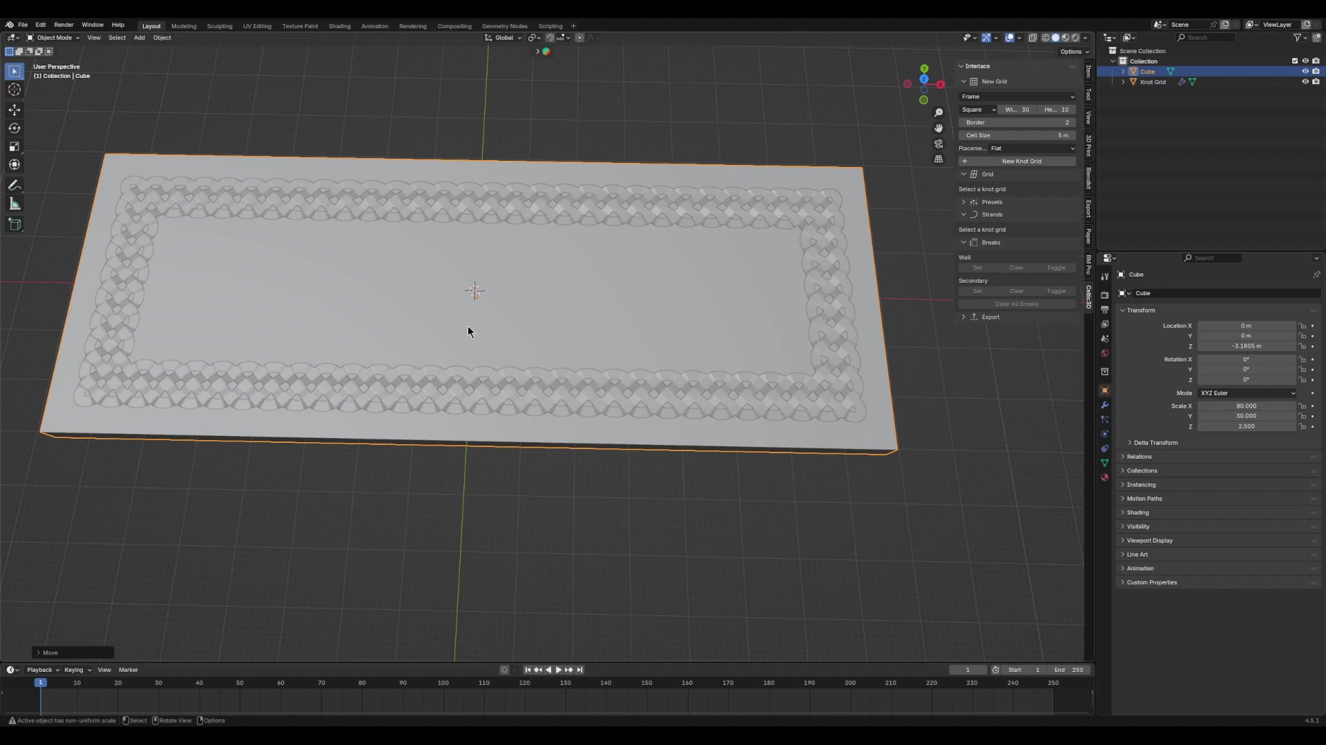
5. Join the parts: why use the Fabrication panel?
I have deliberately kept the unsuccessful attempt to Boolean-join the knotwork directly to the cube in the video. It shows a real modelling difficulty, followed by the better result obtained with the plugin’s Fabrication panel for this plaque.
For the knotwork, use the fabrication controls to build the base and relief together. The demonstration uses a Plate base with an Embossed finish. Check the plate thickness, margin and embed settings against the intended result. Keep the editable knot grid so you can return to the design.
For separate text, place the letters so they overlap the base by a small, deliberate amount. A Boolean Union combines solid lettering with the base; Difference cuts lettering into it. Work on a copy, inspect the result and only then apply the modifier. Blender’s Join command, Ctrl + J, groups meshes into one object but does not fuse their intersecting surfaces.
The comparison is specific to this model. It does not mean that every direct Boolean operation will fail, or that a fabrication result can skip the checks below.
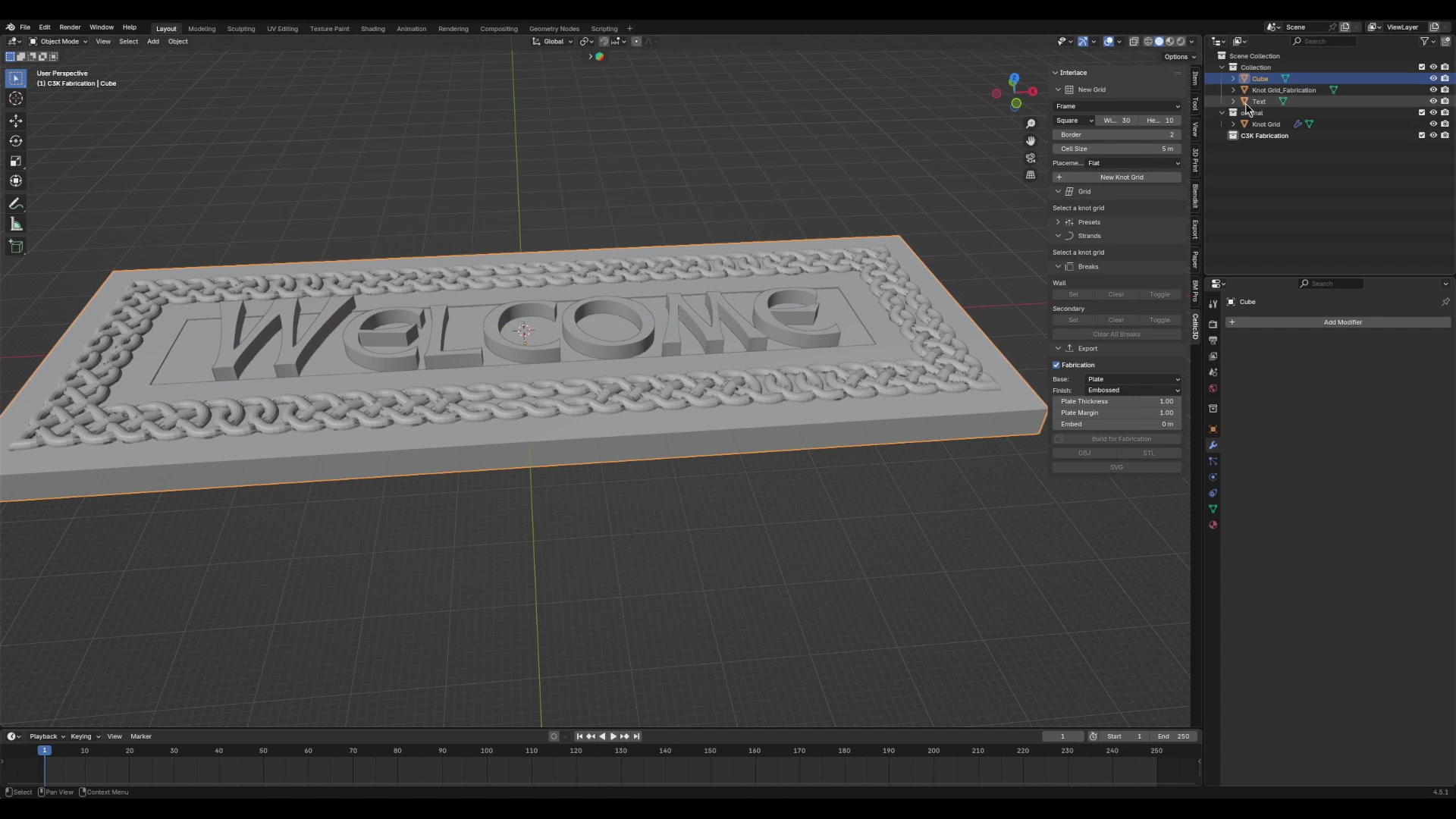
6. Check the geometry with 3D Print Toolbox
Install 3D Print Toolbox from Blender Extensions, maintained by Mikhail Rachinskiy. In Blender 4.5, look under Edit → Preferences → Get Extensions, search for 3D Print Toolbox and install it. Select the final mesh and open its 3D Print sidebar panel to run the checks.
- Manifold surface: for a closed solid, each surface edge should belong to two faces. Look for holes, loose geometry and edges shared by too many faces.
- Intersections: overlapping closed objects may each be manifold while still needing a proper union. A zero non-manifold count does not prove the whole assembly is ready.
- Small or degenerate geometry: inspect the highlighted faces and edges before changing them. Cleanup thresholds must suit the model’s scale.
- Thickness and overhangs: judge these against the printer, material and orientation you will actually use.
A non-planar face is not automatically non-manifold. Likewise, Merge by Distance is a targeted cleanup tool, not a universal repair. Save a copy before cleanup and compare the result, especially around narrow letter strokes and knot crossings.
The recording includes geometry inspection; it is not a completed print test. Check your final model and slicer preview before manufacture.
7. Export STL at the intended size
STL stores coordinates without a reliable millimetre-or-metre label. The exporter’s settings and the receiving program’s interpretation must agree.
- Choose the final geometry. Export the intended fabrication result or completed assembly, leaving out spare bases, editable grids and backup text.
- Know your export route. Celtic3d Knotwork’s own export convention is one Blender unit to one millimetre. Blender’s general STL exporter has separate Scale and Scene Unit controls; these can change the coordinates written to the file.
- Check the receiving application. Open the STL in your slicer and confirm that the plaque measures 160 × 60 mm. Do not accept an automatic rescale without understanding why it was needed.
- Inspect the layer preview. Check that the lettering and border meet the base, and that small features survive slicing.
For the exporter controls, see the Blender 4.5 STL manual. This final size check is useful even when a model looks correct on screen.
Make the project your own
Try a house name, a short greeting or a gift inscription. Change the font and border proportions to suit the words. Celtic3d Knotwork Free is the edition demonstrated here; Celtic3d Knotwork Pro adds closed layouts (rings, cylinders and toruses) and the bevelled, tramline and custom strand profiles.
Everything about the add-on — editions, price, licence — is on the Celtic3d Knotwork page. Questions about the workflow? Get in touch with Celtic3d and include your Blender version and the step you are working on.
About the maker
I’m Gavin Bain. Celtic3d brings together 35 years of corporate IT experience and my passions for digital art, technology, making things and Scottish heritage. This plaque is a small example of how those interests meet: a traditional construction method, a digital tool and something personal to make.