New Licence Options for 3D Downloadable Files
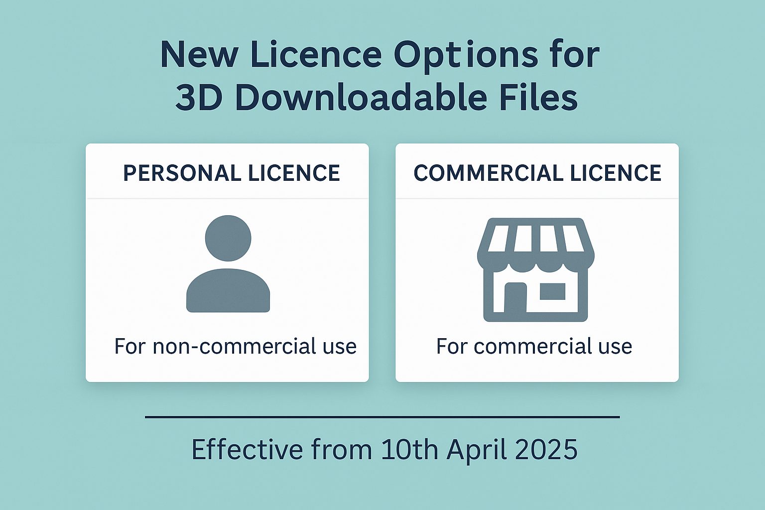
Celtic3d is introducing updated licence terms to better serve both hobbyists and small businesses who use our downloadable 3D model files. Effective from 10th April 2025, all new digital downloads will include a choice between two types of licence: Personal…